Overview
Background
As a member of the vehicle mechanics division, I helped in prototyping, designing, and manfucaturing of various parts of the car. Some projects includes the wheel covers, battery mount, and a composite chassis.
Competition
Our gasoline prototype car competes at Shell Eco-Marathon Americas and SAE. In 2019, we placed 2nd in both competitions with a max mileage of 2229mpg.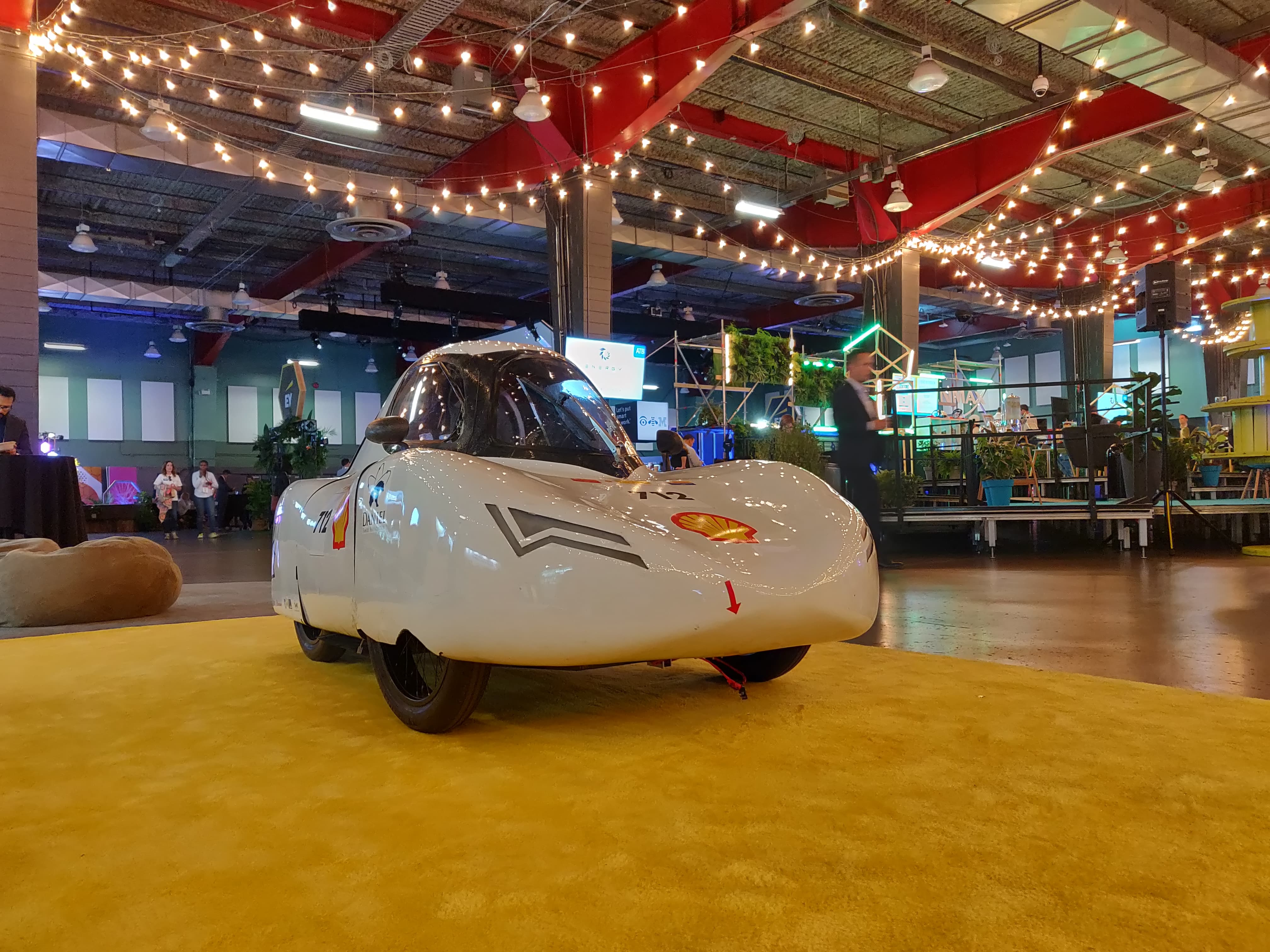
Battery Mount
Objective
The goal was to develop a new, lightweight metal battery mount that is secure the and provides ease of access to the UrbanConcept battery. The battery mount must also abide by both SEMA and SAE competition rules; these rules are always changing. Import design considerations were
- Fire-resistant
- Secures battery
- Quick-access for testing
- Lightweight/cheap
Detailed document found here.
Background Information
The previous battery mount was originally a 3D printed mount. The problem was that it was only strapped down with a velcro which would not pass inspection. Thus a metal mount for the battery that is covered with the LIPO bag was quickly manufactured to pass inspection.
Design and Simulations
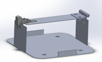
The initial design includes purchasing a snap lock and a hinge from Walmart and MISUMI respectively. We will utilize the small tabs with the taller sides which will be squeezed together by the snap lock. This design is approximately 80% lighter than the previous.
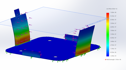
A 35 N (7.7lbs) loading force has been applied to each side which is the weight of the battery weight. Simulating with this weight provides an inherent safety factory because in reality, we would never see a distributed 35 N force at once as simulated above. As you can see, the max stress concentration is 1e+8 Pa but the yield strength is 1.95e+8 Pa. This shows that there is a safety factor of around 2. Given that the snap lock will hold the two larger sides flush to the battery, and it is on these sides where we see the max stress, it will help alleviate the stress and increase the safety factor.
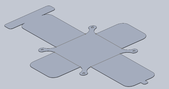
We have created a sheet metal model to input into the water jet cutter as a .dxf file. Using the water jet cutter is more precise and efficient than by hand. This allows manufacturing to become easier.
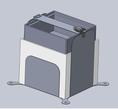
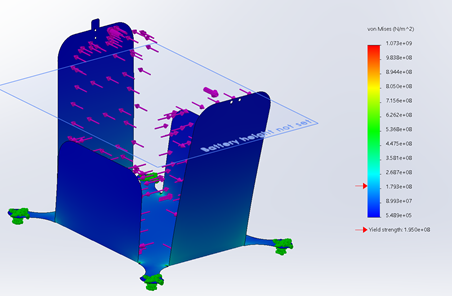
As you can see from above, the final design is taller in order to fit the urban battery configuration. Because the battery configuration changes with different tracks, this means the battery dimension changes as well. The final design is fit for the largest configuration and will utilize 3D printed or foam spacers to fit smaller configurations.
An FEA on the final configuration displays the stress concentration of the final product. The max stress that is higher than the yield stress is located at the small incisions on the corner of the side tabs; these incisions are made for bending tolerance. It is on an extremely small point on the mount and is ignored because the snap lock will hold these larger faces flush to the battery, reducing the stress concentration at those points. Moreover, there is also an inherent safety factor as the loading on each of these faces are the entire weight of the battery, 35N.
Final Product
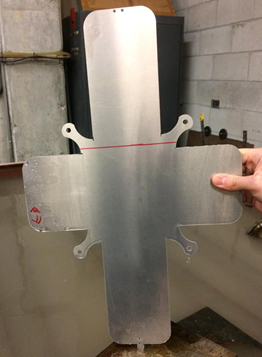
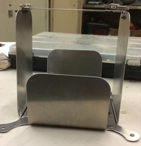
The image above shows the final product of our urban battery mount. Everything except the top piece, snap lock, and hinge is one piece. That sheet metal piece is water jet cut and then bent in the UBC MECH machine shop. M3 bolts were used to attach the hinge and snaplock to the mount. The four corner holes are used to bolt the mount to the chassis.
Wheel Covers
Objective
The goal of this project was to design new wheel covers to fit inside the new proto shell that isolates the driver from the wheels. It must cover the front, inner sides, and the back of the wheel that is exposed to the driver.
Design
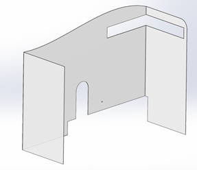
The was made of ~3/16" thick polycarbonate sheets (Lexan) which were directly mounted to the wheel mounts. It is manufcatured and designed to simply shield the driver from the whole wheel.